
- Fiber Optic Cables
- Fiber Optic Cable Accessories
- Copper Cables
- Copper Cable Accessories
- High Density Data Center Wiring System
- Intelligent Management Wiring System
- Security Cables
- Conference AV Cables
- Cabinet and Accessories
- SFP+/QSFP+AOC Active Optical fiber Cable Assemblies
- MPO pre-end modules
- MPO high density optical fiber patch panels
- MPO import adapters
- MTP/MPO Loopback
- MTP/MPO pre-terminated trunk optical cables
- MTP/MPO pre-terminated branch optical cables
- MTP/MPO pre-terminated fanned optical fibers
- QSFP to SFP optical fiber cables
- 40G QSFP+ optical fiber connect cables
- CXP to SFP optical fiber cables
- 100G CXP optical fiber connect cables
- 40G QSFP+ optical fiber connect cables
- IP68 waterproof MPO connector and patch cords
- SFP+/QSFP+DAC Active Copper Cable Assemblies
- MPO high density optical fiber distribution box adapter panels

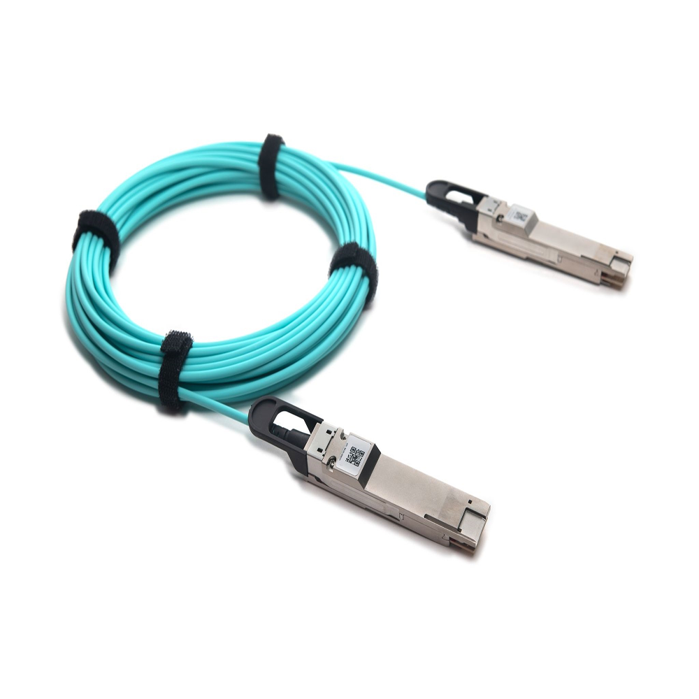
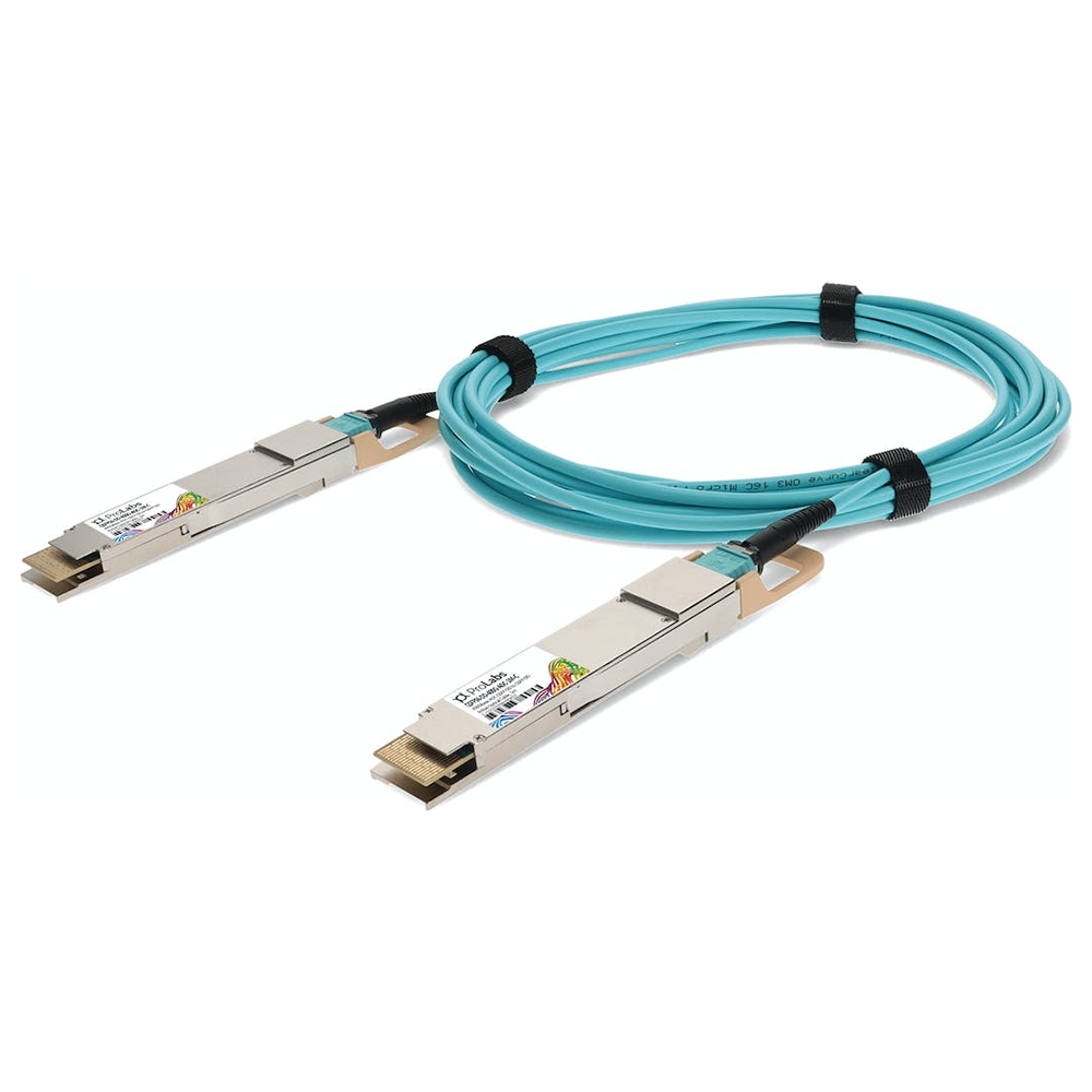
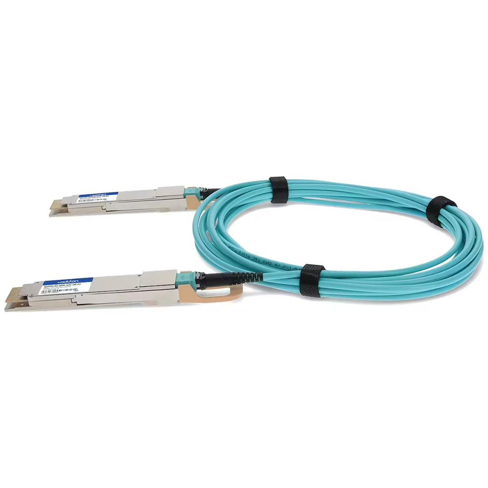
400G QSFP-DD Direct Attach Cable - PAM4 Datasheet
Brand Name:KOLORAPUS
Sample: Available
Unit price<=$15 ,free sample and need to pay the freight.
Unit price >$15,need to pay the double sample fee and freight.
MOQ: >=$7000
Origin: China
Certification:ISO/3C/CE/ROHS/UL
Package: Carton
Payment Method:T/T
General Description
QSFP-DD passive copper cable assembly feature eight differential copper pairs,providing four data transmission channels at speeds up to 56Gbps(PAM4) per channel,and meets 400G Ethernet and InfiniBand Enhanced Data Rate(EDR) requirements.Available in a broad rang of wire gages-from 28AWG through 30AWG-this 400G copper cable assembly features low insertion loss and low cross talk.
QSFP-DD uses PAM4 signals for transmission, which doubles the rate. However, there are more stringent requirements for cable insertion loss. For detailed requirements, please see High Speed Characteristics.
Features and Benefits
l Compatible with IEEE 802.3bj and IEEE 802.3cd
l Supports aggregate data rates of 400Gbps(PAM4)
l Optimized construction to minimize insertion loss and cross talk
l Pull-to-release slide latch design
l 28AWG through 30AWG cable
l Straight and break out assembly configurations available
l Customized cable braid termination limits EMI radiation
l Customizable EEPROM mapping for cable signature
l RoHS omplia
Product Applications
l Switches,servers and routers
l Data Center networks
l Storage area networks
l High performance computing
l Telecommunication and wireless infrastructure
l Medical diagnostics and networking
l Test and measurement equipment
Industry Standards
l 400G Ethernet(IEEE 802.3cd)
l InfiniBand EDR
High Speed Characteristics
Parameter | Symbol | Min | Typical | Max | Unit | Note |
Differential Impedance | TDR | 90 | 100 | 110 | Ώ | |
Insertion loss | SDD21 | -16.06 | dB | At 13.28 GHz | ||
Differential Return Loss | SDD11 SDD22 | See 1 | dB | At 0.05 to 4.1 GHz | ||
See 2 | dB | At 4.1 to 19 GHz | ||||
Common-mode to common-mode output return loss | SCC11 SCC22 | -2 | dB | At 0.2 to 19 GHz | ||
Differential to common-mode return loss | SCD11 SCD22 | See 3 | dB | At 0.01 to 12.89 GHz | ||
See 4 | At 12.89 to 19 GHz | |||||
Differential to common Mode Conversion Loss | SCD21-IL | -10 | dB | At 0.01 to 12.89 GHz | ||
See 5 | At 12.89 to 15.7 GHz | |||||
-6.3 | At 15.7 to 19 GHz | |||||
Notes: 1. Reflection Coefficient given by equation SDD11(dB) < -16.5 + 2 × SQRT(f ), with f in GHz 2. Reflection Coefficient given by equation SDD11(dB) < -10.66 + 14 × log10(f/5.5), with f in GHz 3. Reflection Coefficient given by equation SCD11(dB) < -22 + (20/25.78)*f, with f in GHz 4. Reflection Coefficient given by equation SCD11(dB) < -15 + (6/25.78)*f, with f in GHz 5. Reflection Coefficient given by equation SCD21(dB) < -27 + (29/22)*f, with f in GHz
| ||||||
Pin Descriptions
QSFP-DD Pin Function Definition
Pin | Logic | Symbol | Description |
1 | GND | Ground | |
2 | CML-I | Tx2n | Transmitter Inverted Data Input |
3 | CML-I | Tx2p | Transmitter Non-Inverted Data Input |
4 | GND | Ground | |
5 | CML-I | Tx4n | Transmitter Inverted Data Input |
6 | CML-I | Tx4p | Transmitter Non-Inverted Data Input |
7 | GND | Ground | |
8 | LVTTL-I | ModSelL | Module Select |
9 | LVTTL-I | ResetL | Module Reset |
10 | Vcc Rx | +3.3V Power Supply Receiver | |
11 | LVCMOS- | SCL | 2-wire serial interface clock |
I/O | |||
12 | LVCMOS- | SDA | 2-wire serial interface data |
I/O | |||
13 | GND | Ground | |
14 | CML-O | Rx3p | Receiver Non-Inverted Data Output |
15 | CML-O | Rx3n | Receiver Inverted Data Output |
16 | GND | Ground | |
17 | CML-O | Rx1p | Receiver Non-Inverted Data Output |
18 | CML-O | Rx1n | Receiver Inverted Data Output |
")
19 | GND | Ground | |
20 | GND | Ground | |
21 | CML-O | Rx2n | Receiver Inverted Data Output |
22 | CML-O | Rx2p | Receiver Non-Inverted Data Output |
23 | GND | Ground | |
24 | CML-O | Rx4n | Receiver Inverted Data Output |
25 | CML-O | Rx4p | Receiver Non-Inverted Data Output |
26 | GND | Ground | |
27 | LVTTL-O | ModPrsL | Module Present |
28 | LVTTL-O | IntL | Interrupt |
29 | Vcc Tx | +3.3V Power supply transmitter | |
30 | Vcc1 | +3.3V Power supply | |
31 | LVTTL-I | LPMode | Low Power Mode |
32 | GND | Ground | |
33 | CML-I | Tx3p | Transmitter Non-Inverted Data Input |
34 | CML-I | Tx3n | Transmitter Inverted Data Input |
35 | GND | Ground | |
36 | CML-I | Tx1p | Transmitter Non-Inverted Data Input |
37 | CML-I | Tx1n | Transmitter Inverted Data Input |
38 | GND | Ground | |
39 | GND | Ground | |
40 | CML-I | Tx6n | Transmitter Inverted Data Input |
41 | CML-I | Tx6p | Transmitter Non-Inverted Data Input |
42 | GND | Ground | |
43 | CML-I | Tx8n | Transmitter Inverted Data Input |
44 | CML-I | Tx8p | Transmitter Non-Inverted Data Input |
45 | GND | Ground | |
46 | Reserved | ||
47 | VS1 | ||
48 | VccRx1 | +3.3V Power supply | |
49 | VS2 | ||
50 | VS3 | ||
51 | GND | Ground | |
52 | CML-O | Rx7p | Receiver Non-Inverted Data Output |
53 | CML-O | Rx7n | Receiver Inverted Data Output |
54 | GND | Ground | |
55 | CML-O | Rx5p | Receiver Non-Inverted Data Output |
56 | CML-O | Rx5n | Receiver Inverted Data Output |
57 | GND | Ground | |
58 | GND | Ground | |
59 | CML-O | Rx6n | Receiver Inverted Data Output |
60 | CML-O | Rx6p | Receiver Non-Inverted Data Output |
61 | GND | Ground | |
62 | CML-O | Rx8n | Receiver Inverted Data Output |
63 | CML-O | Rx8p | Receiver Non-Inverted Data Output |
64 | GND | Ground | |
65 | NC | ||
66 | Reserved | ||
67 | VccTx1 | +3.3V Power supply | |
68 | VCC2 | +3.3V Power supply | |
69 | Reserved | ||
70 | GND | Ground | |
71 | CML-I | Tx7p | Transmitter Non-Inverted Data Input |
72 | CML-I | Tx7n | Transmitter Inverted Data Input |
73 | GND | Ground | |
74 | CML-I | Tx5p | Transmitter Non-Inverted Data Input |
75 | CML-I | Tx5n | Transmitter Inverted Data Input |
76 | GND | Ground |
Mechanical Specifications
The connector is compatible with the QSFP-DD specification.
")
Regulatory Compliance
Feature | Test Method | Performance |
Electrostatic Discharge (ESD) to the Electrical Pins |
MIL-STD-883C Method 3015.7 |
Class 1(>2000 Volts) |
Electromagnetic Interference(EMI) | FCC Class B | Compliant with Standards |
CENELEC EN55022 Class B | ||
CISPR22 ITE Class B | ||
RF Immunity(RFI) |
IEC61000-4-3 | Typically Show no Measurable Effect from a 10V/m Field Swept from 80 to 1000MHz |
RoHS Compliance | RoHS Directive 2011/65/EU and it's Amendment Directives (EU) 2015/863 | RoHS (EU)2015/863 compliant |
REACH Compliance | REACH Regulation (EC) No 1907/2006 | REACH (EC) No 1907/2006 compliant |